14-54 Inch A-USP1 RWGV FLxFL
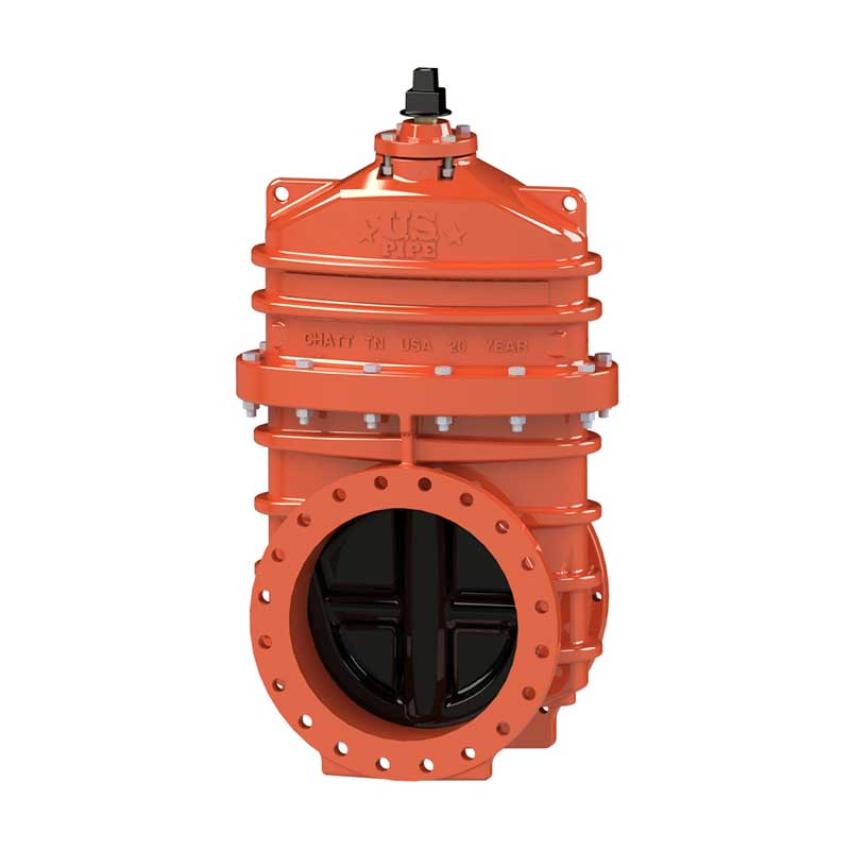
14-54 Inch A-USP1 RWGV FLxFL
Specifications:
- Flanged ends
- Sizes – 14", 16", 18", 20", 24", 30", 36", 42", 48", 54"
- Meets or exceeds all applicable requirements of ANSI/AWWA C515 Standard (thru 48”), UL 262 Listed (thru 24”), FM 1120/1130 Approved (thru 24”), and certified to ANSI/NSF 61 & 372
- Flanged end dimensions and drilling complies with ASME/ANSI B16.1 Class 125
- Ductile iron body and bonnet with nominal 10 mils Pro-Gard® Fusion Bonded Epoxy coating interior and exterior surfaces; 42" – 54" valves coated with HP Epoxy coating.
- Epoxy coatings meet or exceed all applicable requirements of ANSI/AWWA C550 Standard.
- Ductile iron wedge, symmetrical & fully encapsulated with molded rubber; no exposed iron.
- Non-rising stem (NRS)
- Triple O-ring seal stuffing box (2 above the thrust collar and 1 below)
- 2" square wrench nut (optional bevel or spur gearing) – open left or open right 30" - 54" require a Spur Gear or Bevel Gear
- 250 psig (1725 kPa/17 barg) maximum working pressure, 500 psig (3400 kPa/34 barg) static test pressure
- 14" and 16" sizes – UL Listed, FM Approved: 250 psig (1725 kPa/17 barg)
- 18", 20" and 24" sizes – UL Listed/FM Approved: 175 psig (1200 kPa/12 barg); FM Approved 250 psig (1725 kPa/17 barg)
- Designed for potable water applications
Options*:
- Stem Options:
- 14"-16" low zinc, silicon bronze ASTM B98-C66100/H02
- 18"-54" low zinc, silicon bronze ASTM B763-C99500 Stainless
- Stainless Steel Type 304, Type 316
- Stainless steel fasteners: Type 316
- Bypass 16"- 54" (2" on 16"-20"; 2.5" on 24"; 3" on 30"- 36", 4" on 42"-54")
- Spur or bevel geared actuator
- EPDM Disc and O-rings, 14"-16" optional, 18"-54" standard
- Position indicators
- Handwheel
Resources:
- Operating Manual
- Product Specifications
- Suggested Specifications
- Installation Preparation Check List
- Submittal Drawing 1: (U536570-316)
- Submittal Drawing 2: (U6956)
- Submittal Drawing 3: (U6702-E302)
- Submittal Drawing 4: (U6750-E302)
- Submittal Drawing 5: (U7225)
- Submittal Drawing 6: (U7300)
- Submittal Drawing 7: (U7405)
- Submittal Drawing 8: (U7421)
- Submittal Drawing 9: (U7422)
- Submittal Drawing 10: (U7450)
- Submittal Drawing 11: (U7451)
- Flyer
- Certification of Compliance: 14" - 24"
- Certification of Compliance: 30" - 54"

Dimension* | Nominal Size | |||||||||
| 14" | 16" | 18" | 20" | 24" | 30"† | 36"† | 42"† | 48"† | 54"† | |
| A | 32.75 | 37.88 | 44.19 | 48.25 | 53.88 | See A for Spur or Bevel Gear | ||||
| R | 21.00 | 23.50 | 25.00 | 27.50 | 32.00 | 38.75 | 46.00 | 53.00 | 59.50 | 66.34 |
| FF | 15.06 | 16.06 | 17.00 | 18.00 | 20.00 | 26.00 | 30.00 | 38.00 | 43.00 | 48.00 |
| Q (bore) | 14.38 | 16.00 | 18.38 | 20.38 | 24.38 | 30.38 | 36.38 | 42.38 | 48.38 | 48.38 |
| UU (bolt circle diameter) | 18.75 | 21.25 | 22.75 | 25.00 | 29.50 | 36.00 | 42.75 | 49.50 | 56.00 | 62.76 |
| B (number and size of holes) | 12--1.125 | 16--1.125 | 16--1.25 | 20--1.25 | 20--1.38 | 28--1.38 | 32--1.63 | 36--1.63 | 44--1.63 | 44--2.00 |
| A- Spur Gear | 40.49 | 43.58 | 49.41 | 53.01 | 59.15 | 70.81 | 83.08 | 97.74 | 109.70 | 109.70 |
| A - Bevel Gear** | 34.55 | 37.77 | 44.50 | 47.69 | 54.06 | 64.93 | 77.19 | 90.75 | 102.61 | 102.61 |
| Turns to open (without gearing) | 43.5 | 49 | 57 | 63 | 75 | - | - | - | - | - |
| Turns to open (Spur gearing) †† | 178 | 201 | 234 | 258 | 308 | 381 | 455 | 524 | 596 | 596 |
| Turns to open (Bevel gearing) †† | 174 | 196 | 228 | 252 | 300 | 372 | 444 | 524 | 596 | 596 |
| Weight* | 690 | 859 | 1284 | 1774 | 2481 | 6390 | 8220 | 13400 | 19978 | 20900 |
**Center line of operating nut to center line of valve.
†Spur or Bevel Gear must be used with 30", 36", 42", 48" & 54" valves.
††Turns shown for bevel gearing. All sizes - 4:1 ratio.

Catalog Part No. | Description | Material | Material Standard |
G-16 | Bonnet Bolts & Nuts | 316 Stainless steel | ASTM F593 (bolt) ASTM F594 (nut) |
G-41 | Stuffing Box Bolts & Nuts | 316 Stainless steel | ASTM F593 (bolt) ASTM F594 (nut) |
G-49 | Stem O-rings (3) ^ | Nitrile | ASTM D2000 |
G-200 | Wrench Nut Cap Screw | 316 Stainless steel | ASTM F593 |
G-201 | Stuffing Box O-ring ^ | Nitrile | ASTM D2000 |
G-202 | Wrench Nut | Cast Iron+ | ASTM A126 CL.B |
G-203 | Stem | Bronze | ASTM B138** |
G-204 | Hand Wheel (not shown) | Cast Iron+ | ASTM A126 CL.B |
G-205 | Stem Nut | Bronze | ASTM B62 |
G-206 | Guide Cap Bearings | Acetal | - |
G-207 | Stuffing Box | Ductile Iron++ | ASTM A536 ▼ |
G-208 | Anti-friction Washers (2) | Acetal | - |
G-209 | Wedge, Rubber Encapsulation | Ductile Iron* SBR ^ | ASTM A536 ▼ ASTM D2000 |
G-210 | Bonnet | Ductile Iron | ASTM A536 ▼ |
G-211 | Bonnet O-ring ^ | Nitrile | ASTM D2000 |
G-212 | Body | Ductile Iron | ASTM A536 ▼ |
^ 18”-54” EPDM standard
++ 30”-54” are hot rolled steel ASTM A36
** 18”-54” ASTM B584
*** 14”-16” valves are provided with 316 stainless steel fasteners as standard
+ Manufacturers option to change material to Ductile iron ASTM A536
▼ Material strength ASTM A536 65-45 minimum