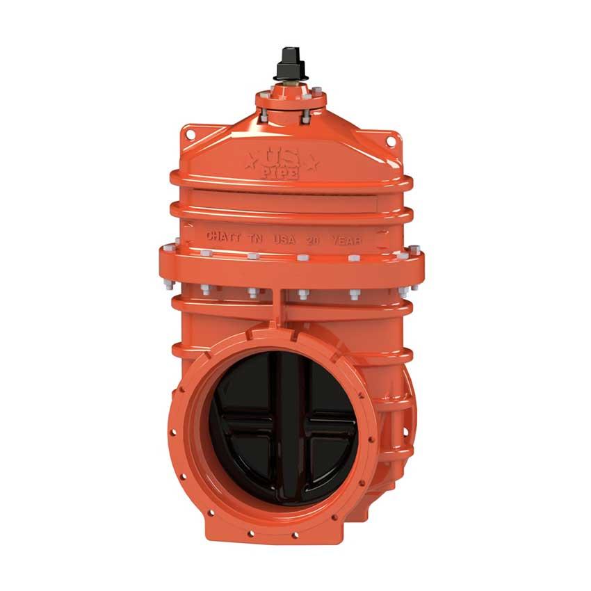
14-48 Inch A-USP1 RWGV MJxFL

14-48 Inch A-USP1 RWGV MJxFL
Catalog numbers:
- A-USP1-16 mechanical joint x flanged ends (with accessories unassembled)
- A-USP1-19 mechanical joint x flanged ends (less accessories)
Specifications:
- Sizes – 14", 16", 18", 20", 24", 30", 36", 42", 48"
- Meets or exceeds all applicable requirements of ANSI/AWWA C515 Standard, UL 262 Listed (thru 24”), FM 1120/1130 Approved (thru 16”), and certified to ANSI/NSF 61 & 372.
- Flanged end drilling complies with ASME/ANSI B16.1 class 125 and B16.42 class 150
- Mechanical joint end complies with ANSI/AWWA C111 Standard
- Ductile iron body and bonnet with nominal 10 mils Pro-Gard® Fusion Bonded Epoxy coated interior and exterior surfaces; 42" and 48" valves coated with HP Epoxy coating.
- Epoxy coating meets or exceeds all applicable requirements of ANSI/AWWA C550 Standard.
- Ductile iron wedge, symmetrical & fully encapsulated with molded rubber; no exposed iron.
- Non-rising stem (NRS)
- Triple O-ring seal stuffing box (2 above the thrust collar and 1 below)
- 2" square wrench nut (optional bevel or spur gearing) – open left or open right 30" - 48" require a Spur Gear or Bevel Gear
- 250 psig (1725 kPa/17 barg) maximum working pressure, 500 psig (3450 kPa/34 barg) static test pressure
- 14" and 16" sizes – UL Listed, FM Approved: 250 psig (1725 kPa/17 barg)
- 18", 20" and 24" sizes – UL Listed: 175 psig (1200 kPa/12 barg); FM Approved: 250 psig (1725 kPa/17 barg)
- Designed for potable water application
Options*:
- Low zinc, silicon bronze ASTM B98-C66100/H02 stem: 14”-16”, ASTM B763-C99500: 18”- 48”
- Stainless Steel Stem Type 304, Type 316: 14"-48"
- Bypass 16” - 48” (2” on 16”-20”; 2.5” on 24”; 3” on 30”- 36”, 4” on 42”-48”)
- EPDM Disc and O-rings, 14”-16” optional, 18”-48” standard
- Handwheel
- Spur or bevel geared actuator
- Position indicators
Resources:
- Operating Manual
- Product Specifications
- Suggested Specifications
- Installation Preparation Check List
- Submittal Drawing 1: (U6956)
- Submittal Drawing 2: (U536570-316)
- Submittal Drawing 3: (U6702-E302)
- Submittal Drawing 4: (U6750-E302)
- Submittal Drawing 5: (U7225)
- Submittal Drawing 6: (U7300)
- Submittal Drawing 7: (U7405)
- Submittal Drawing 8: (U7421)
- Submittal Drawing 9: (U7422)
- Submittal Drawing 10: (U7450)
- Submittal Drawing 11: (U7451)
- Brochure
- Certification of Compliance: 14" - 24"
- Certification of Compliance: 30" - 54"

Dimension | Nominal Size | ||||||||
14" | 16" | 18" | 20" | 24" | 30"† | 36"† | 42"† | 48"† | |
| A | 32.75 | 37.88 | 44.19 | 48.25 | 53.88 | See A for Spur or Bevel Gear | |||
| L | 3.50 | 3.50 | 3.50 | 3.50 | 3.50 | 4.00 | 4.00 | 4.00 | 4.00 |
| N | 20.66 | 22.66 | 24.88 | 27.25 | 31.88 | 39.53 | 46.41 | 53.53 | 60.41 |
| O (number and size of holes for MJ) | 10--.88 | 12--.88 | 12--.88 | 14--.88 | 16--.88 | 20--1.125 | 24--1.125 | 28--1.38 | 32--1.38 |
| Q (bore) | 14.38 | 16.00 | 18.38 | 20.38 | 24.38 | 30.38 | 36.38 | 42.38 | 48.38 |
| OO (bolt circle diameter for MJ) | 18.75 | 21.00 | 23.25 | 25.50 | 30.00 | 36.88 | 43.75 | 50.62 | 57.50 |
| R | 21.00 | 23.50 | 25.00 | 27.50 | 32.00 | 38.75 | 46.00 | 53.00 | 59.50 |
| UU (bolt circle diameter) | 18.75 | 21.25 | 22.75 | 25.00 | 29.50 | 36.00 | 42.75 | 49.50 | 56.00 |
| FF | 17.41 | 17.91 | 19 | 19.75 | 21.75 | 29.75 | 33.75 | 40.19 | 43.86 |
| B (number and size of holes for FL) | 12--1.12 | 16--1.12 | 16--1.12 | 20--1.25 | 20--1.38 | 28--1.38 | 32--1.63 | 36--1.63 | 44--1.63 |
| A - Spur Gear | 40.49 | 43.58 | 49.41 | 53.01 | 59.15 | 70.81 | 83.08 | 97.74 | 109.70 |
| A - Bevel Gear** | 34.55 | 37.77 | 44.50 | 47.69 | 54.06 | 64.93 | 77.19 | 90.75 | 102.61 |
| Turns to open (without gearing) | 43.5 | 49 | 57 | 63 | 75 | - | - | - | - |
| Turns to open (Spur gearing) | 178 | 201 | 234 | 258 | 308 | 381 | 455 | 524 | 596 |
| Turns to open (Bevel gearing) †† | 174 | 196 | 228 | 252 | 300 | 372 | 444 | 524 | 596 |
| Weight* | 693 | 850 | 1279 | 1795 | 2459 | 6457 | 8412 | 13083 | 19841 |
**Center line of operating nut to center line of valve.
†Spur or Bevel Gear must be used with 30", 36", 42", 48" valves.
††Turns shown for Bevel gearing. Valves with Bevel gearing: All Sizes - 4:1 ratio.
Catalog Part Number | Description | Material | Material Standard |
G-16 | Bonnet Bolts & Nuts | 316 Stainless Steel | ASTM F593 (bolt) ASTM F594 (nut) |
G-41 | Stuffing Box Bolts & Nuts | 316 Stainless Steel | ASTM F593 (bolt) ASTM F594 (nut) |
G-49 | Stem O-rings (3) ^ | Nitrile | ASTM D2000 |
G-200 | Wrench Nut Cap Screw | 316 Stainless Steel | ASTM F593 |
G-201 | Stuffing Box O-ring ^ | Nitrile | ASTM D2000 |
G-202 | Wrench Nut | Cast Iron+ | ASTM A126 CL.B |
G-203 | Stem | Bronze | ASTM B138** |
G-204 | Hand Wheel (not shown) | Cast Iron+ | ASTM A126 CL.B |
G-205 | Stem Nut | Bronze | ASTM B62 |
G-206 | Guide Cap Bearings | Acetal | - |
G-207 | Stuffing Box | Ductile Iron++ | ASTM A536 ▼ |
G-208 | Anti-friction Washers (2) | Acetal | - |
G-209 | Wedge, Rubber Encapsulation | Ductile Iron* SBR ^ | ASTM A536 ▼ ASTM D2000 |
G-210 | Bonnet | Ductile Iron | ASTM A536 ▼ |
G-211 | Bonnet O-ring ^ | Nitrile | ASTM D2000 |
G-212 | Body | Ductile Iron | ASTM A536 ▼ |
**18" - 48" ASTM B584
*** 14”-16” valves are provided with 316 stainless steel fasteners as standard
^18" - 48" EPDM standard
++ 30”-48” are hot rolled steel ASTM A36
+ Manufacturers option to change material to Ductile iron ASTM A536
▼ Material strength ASTM A536 65-45 minimum


